6 Volt Electronic Ignition Circuit Diagram
(Wiring Diagram, Pertronix 6 volt Ignitor 1188P6 )
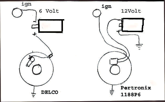
Wiring schematic for 6 volt, Positive Ground, Pertronix Ignitor ( 1188P6 )
Original wiring is from IGN switch (coil term) to (-) term on 6 volt coil. (+) term on 6 volt coil to distributor, to points, which are grounded on one side.
New schematic-
Connect IGN switch (coil term) to black wire from ignitor module / the Black/ white wire from the Ignitor module connects to the (-) terminal on the NEW 12* volt Coil. The (+) terminal on the 12 Volt coil has to have a NEW wire fabricated, connecting it to the chassis (gnd) or the (+) Battery terminal (*) Pertronix was questioned on the 12 volt coil, which was sent with the application. They state there isn't really any difference between a 6 or a 12 volt coil. It has to do with the primary resistance circuit within the coil itself.
Sometime in April, after I had spoken to 2-3 techs at Pertronix, they called me and agreed to make a custom unit for the 6 volt, positive ground system in my 55 President. They needed info on the distributor, car model, etc. I took the Delco information right out of the shop manual ( #1110839).
After a couple weeks, I called back and they,indeed, had a production number ready to go. They said to order the unit through any dealer and specify the production number 1188P6, as the catalogs would not have it listed yet.
I ordered the unit through Ted Harbit ( our dealer) and hoped to pick it up at South bend, but had to wait a bit longer.
The kit arrived in July and consists of the electronic switch, a magnetic collar that fits over the distributor cam and some screws, terminals, etc.
The only issue was the magnetic collar that fits over the steel cam, which previously opened the points. This collar is a press fit right over the octagon steel cam and triggers the electronic module, using 8 tiny magnets in the perimeter.
The trouble came when the rotor was to be installed. The rotor has an internal tab that fits into the top of the steel post above the point cam. The hole in the top of the magnetic collar wasn't large enough to allow the rotor to slide all the way down and fully seat onto the steel post, subsequently not allowing the distributor cap to be installed.
A call to Pertronix ( and they were receptive to working things out). The hole in the collar was 21MM, the base of the rotor was 22MM and slightly tapered. They stated that you could file the internal diameter of the collar larger, but I elected to file the rotor until it had an interference fit into the magnetic collar and fully seated.
Pertronix should have realized that I was telling them about a problem, which I WASN'T aware of. This was the fact that with the collar couldn't fit far enough down on the steel cam to trigger the control unit.
After realizing what the fit should be, the collar was modified, set in place, with the rotor and cap. Everything worked on the first crank
It Works
Source: https://www.studebaker-info.org/Tech/6-12V/Pert6v.html
Posted by: eabygailnoes.blogspot.com

Posting Komentar untuk "6 Volt Electronic Ignition Circuit Diagram"